Hovert60 keyboard devlog #2: Design
Table of Contents
Overview
In the previous post on the topic, I introcuded my new project: making a personalized mechanical keyboard from scratch. I described my criteria for the end result and showed you the components I intend to use.
This post is focused on the design process of the project. The posts are sequential, but in reality they go hand-in-hand. The design influences which components can be used. Availability, price and properties of the components influence the design.
This interconnection extends past the «preparation» and «design» stages. In reality, I am in the beginning of the «manufacture» stage at the moment of writing this, and I still have to make purchases and revisit the design.
This post will cover these stages:
- Finding inspiration and collecting data
- Choosing how to manufacture the parts
- Learning-by-doing with Autodesk Fusion
- Iterating on the design until I’m happy
Where do I even begin?
What’s the shape of my hand?
In the previous post I mentioned a tool called Cosmos. There is also a type of keyboard called Dactyl. These things have a common trait: they are made for tweaking & personalization. So I thought, why don’t I try to do personalize my keyboard?
I drew some dots on the joints of my hand (and a few extra ones). Then I put a ruler on a wall and took some photos of my hand next to the ruler. To decrease the influence of perspective on the resulting image, I took the photos from afar with high level of zoom.
After I had the photos of various positions of my hand (relaxed, flat, stretched, contracted), I traced the dots I drew into hand shapes in Inkscape. Thanks to the ruler in the photos, I was able to scale the results quite precisely.
Some fiddling with it later, I tried to estimate the paths that my fingertips should follow when moving. When I saw the paths, I understood that I don’t want to use this approach anymore. Maybe next time. At that moment it was too advanced for me.

An example of a hand traced in various positions. Thick grey lines represent favoured fingertip movement paths.
Can I use a laser cutter?
At first I was considering using a sheet of wood or acrylic for the top plate of the keyboard. Prototyping something with a laser cutter would also be easier than with a CNC router. So I started by drawing a test pattern to find what size of the holes I should use.

Holes of different sizes to check laser cutter tolerance. For actual testing, line thickness should be set to «hairline», but I changed it here for better visibility.
However, as I was about to perform the test, I learned that with the thickness of the plate I wanted, neither wood or acrylic would be reliable options. I could opt-in for a thicker plate and give up the idea of making the key switches click in place, but at that moment, the idea of making the front plate out of metal using a CNC router took over.
Going with metal
So, I decided to use metal. As I mentioned in the previous post, my metal of choice is brass. However, I still bought a few sheets of acrylic (3mm thick) and two plates of 6061 aluminium (1.5mm thick) for testing.
At this point, the front plate stopped being 2D. In a laser cutter, the depth of the cut is controlled by changing the speed with which the laser moves. In a CNC router, the milling bit moves on 3 axes. As I also wanted the switches to snap into their holes, I wanted to add special keyswitch lock grooves. This meant that some cutting movements wouldn’t reach the bottom of the stock.
It was time to learn a new tool: Autodesk Fusion.
Picking up Autodesk Fusion
For a few first minutes, the program was a bit confusing. I intend to make 3D models, are 2D sketches really the way to go? Why isn’t it something like Blender? However, after watching a random tutorial, things started making more sense. With sketches, it’s easy to define sizes and constraints for different features.
Terminology used
Please note that these definitions are contextual and may be incomplete.
Plane
Plane is a flat surface that extends indefinitely.
There are three «main» planes: XY, XZ and YZ. They intersect with the origin and contain the corresponding axes.
Planes can be based on various surfaces of the model designed.
Sketch
Sketch is a 2-dimensional drawing. Each sketch is made on some plane.
When a sketch is finished, various commands like «Extrude» can reference its features.
To work well, sketches should be «fully constrained». When making a sketch, the user can generally do two things:
- Draw various points, lines and shapes
- Specify constraints between drawn things
Some examples of constraints are:
- Length of a line (you can see lots of these in the next illustration)
- Distance between lines or between a line and a point
- Lines being parallel or perpendicular
- Lines and points being incident
- Lines being tangential to curves
The program accumulates this data and tries to figure out how to place all the parts of the drawing in a way that complies with the constraints. When there is enough information for the program to resolve all uncertainities, the sketch is considered to be «fully constrained».
«Extrude» command
«Extrude» is the primary command that allows turning 2D sketches into 3D shapes. In the most general case, it allows specifying thickness to be used for selected areas of an existing sketch. It can also be used to cut into the model.
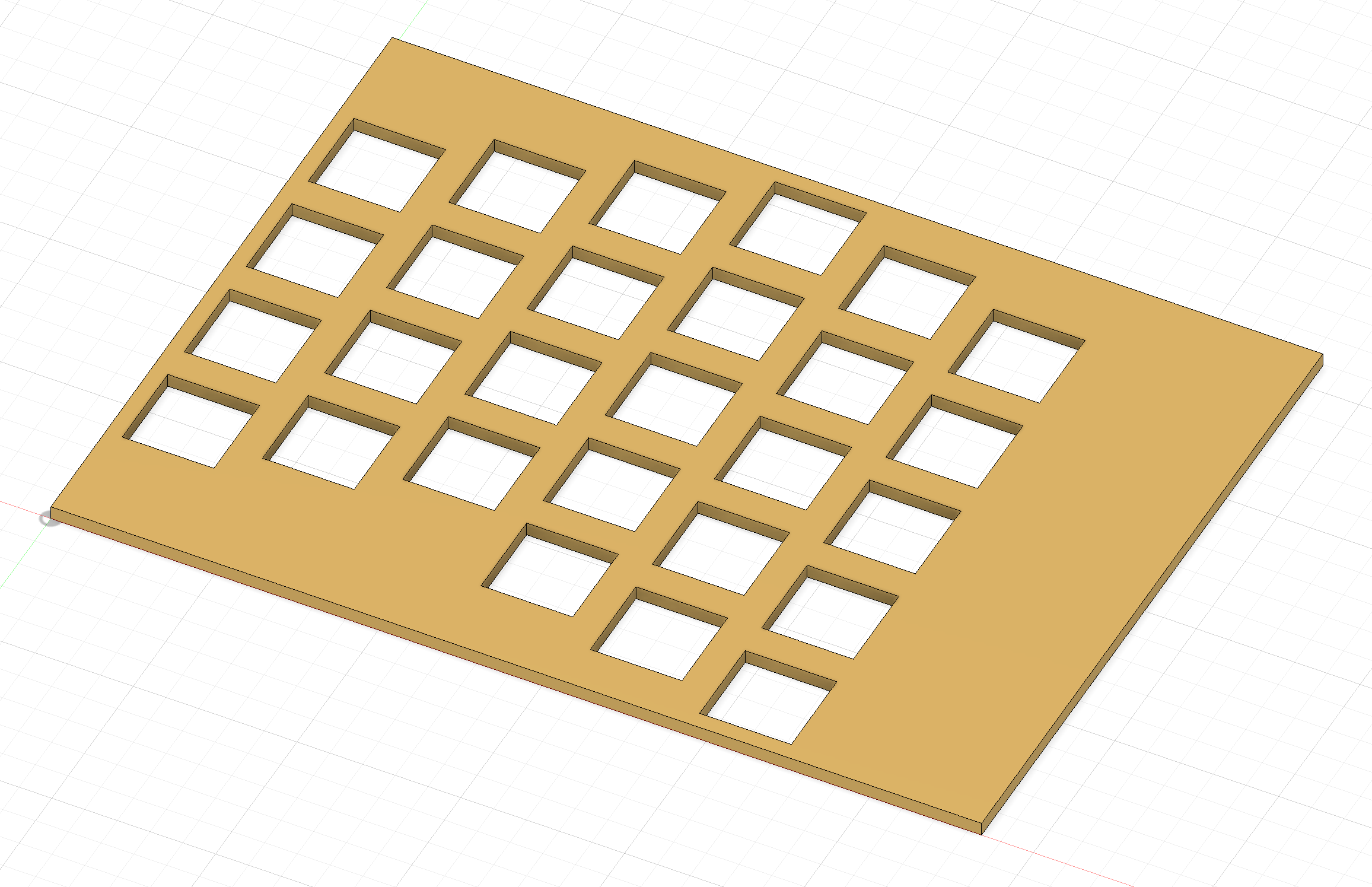
I started by creating a flat piece of material of random width and length and known thickness. I then sketched square holes for the keys on the surface of that piece.
Sketching the holes for the bottom row of keys
After I had the sketch for holes, I was able to use the Extrude command to cut them out of the existing plate. Then, by using a Rectangular pattern command, I repeated the cutting operation 4 times on the Y axis using some offset.
Repeating cutouts along the Y axis
It just makes sense
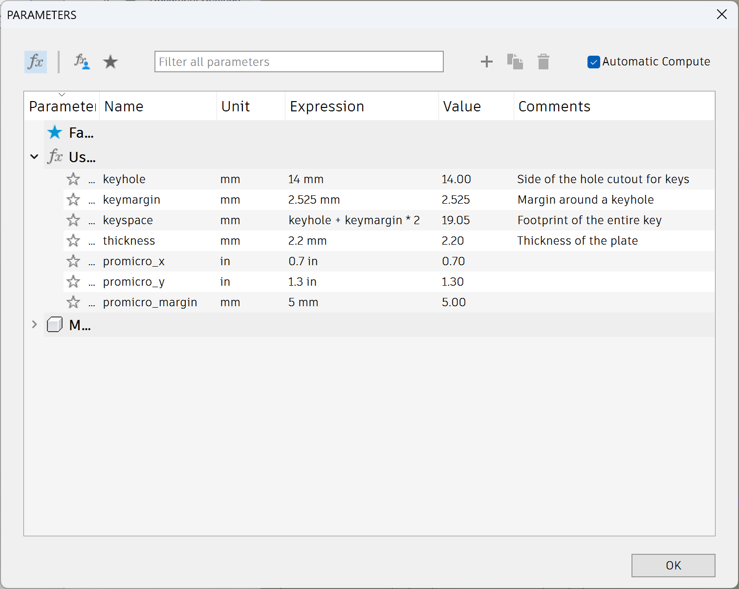
At this point I found out that I can specify variables to be reused when settings constraints and configuring various commands. This greatly sped up the development process. I could adjust dimensions in multiple places at the same time.
On top of that, formulas for these variables can contain mentions of other variables! This way I could give names to common values that depended on other values.
One of such values is the width and length of the area occupied by a key, which includes the key hole and a margin around it.
That parameter is called keyspace in the next illustration.
Discovering parameters
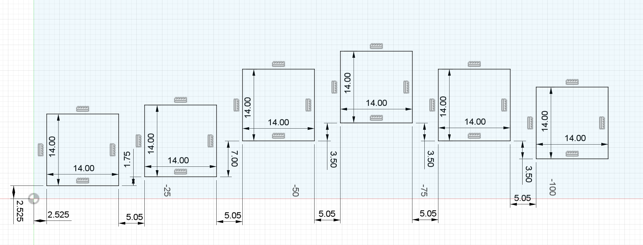
After I got the first batch of parameters specified, I added them to my sketch.
Dimensions that are prefixed with fx: in the next screenshot are those that use parameters (so, all of them).
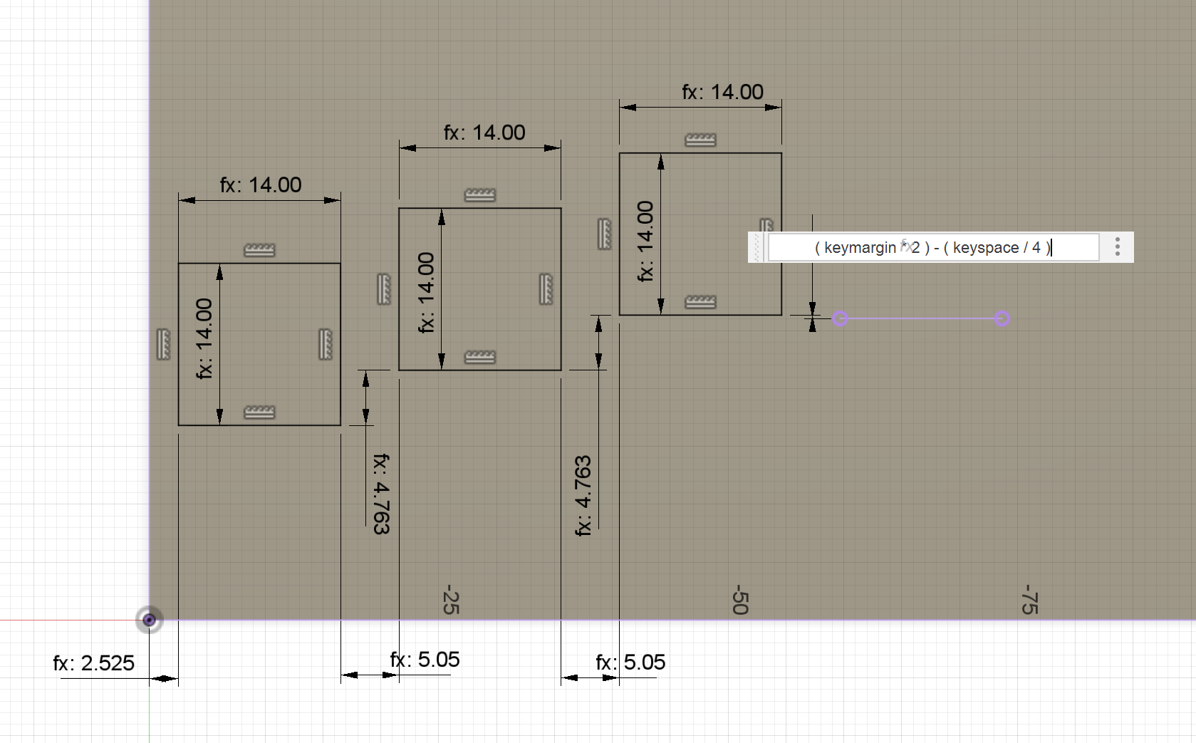
Using parameters in a sketch
As you can see, I decided to design a single row of keys, and then duplicate these rows.
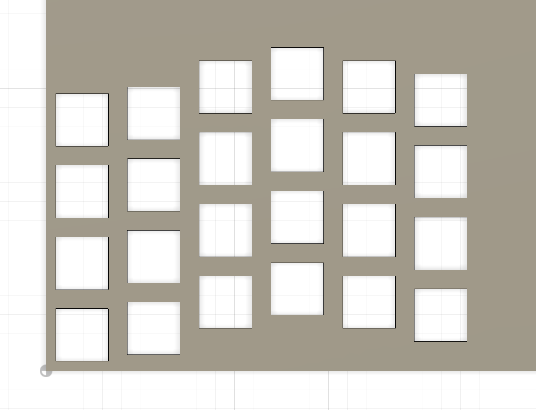
In the following picture you can see the design that I came to after doing parameter magic. You can also see that columns 4, 5 and 6 are one key taller. The 3 extra keys were the initial version of the thumb cluster – a group of keys that are meant to be pressed with the thumb.
Trying to design the thumb cluster
When I arrived to this complex shape, I realized that I don’t like the approach of «cut out the holes in a predefined plate» I have been using. If I wanted to continue, I would need to define parameters that would define the initial dimensions of the plate. And I would also need to strip down quite a lot of material from the plate to have a nice outline.
It would get even worse if I wanted to design a more advanced thumb cluster. I would have to use even more complex calculations to determine the initial size of the plate, or I’d have to do intermediate Extrusions to stretch out the plate and make space for more keys.
I didn’t want to deal with any of that, so I decided to try an alternative approach.
Additive design approach
The new design approach of my choice can be described as «additive». To me, this means that I start with something small and extend it, compared to starting with something big followed by reducing it.
The approaches are not strictly distinct from each other. I can still remove material, such as when I add fillets. It’s just that there are many ways to reach the goal, and as the manufacture stage is separate from design stage, the choice should simply be «whatever works best».
The following illustration shows 4 rows of parallel key holes and 1 row of key holes that are not aligned straight. The 3 out of 4 parallel rows are duplicates of the bottom one. The curved row is meant for the thumb.
You can see how the rows have thin black lines between them. That’s because at the moment of taking the screenshot, they are all individual bodies. However, this is not a problem, as they can be joined into a single body with a command.
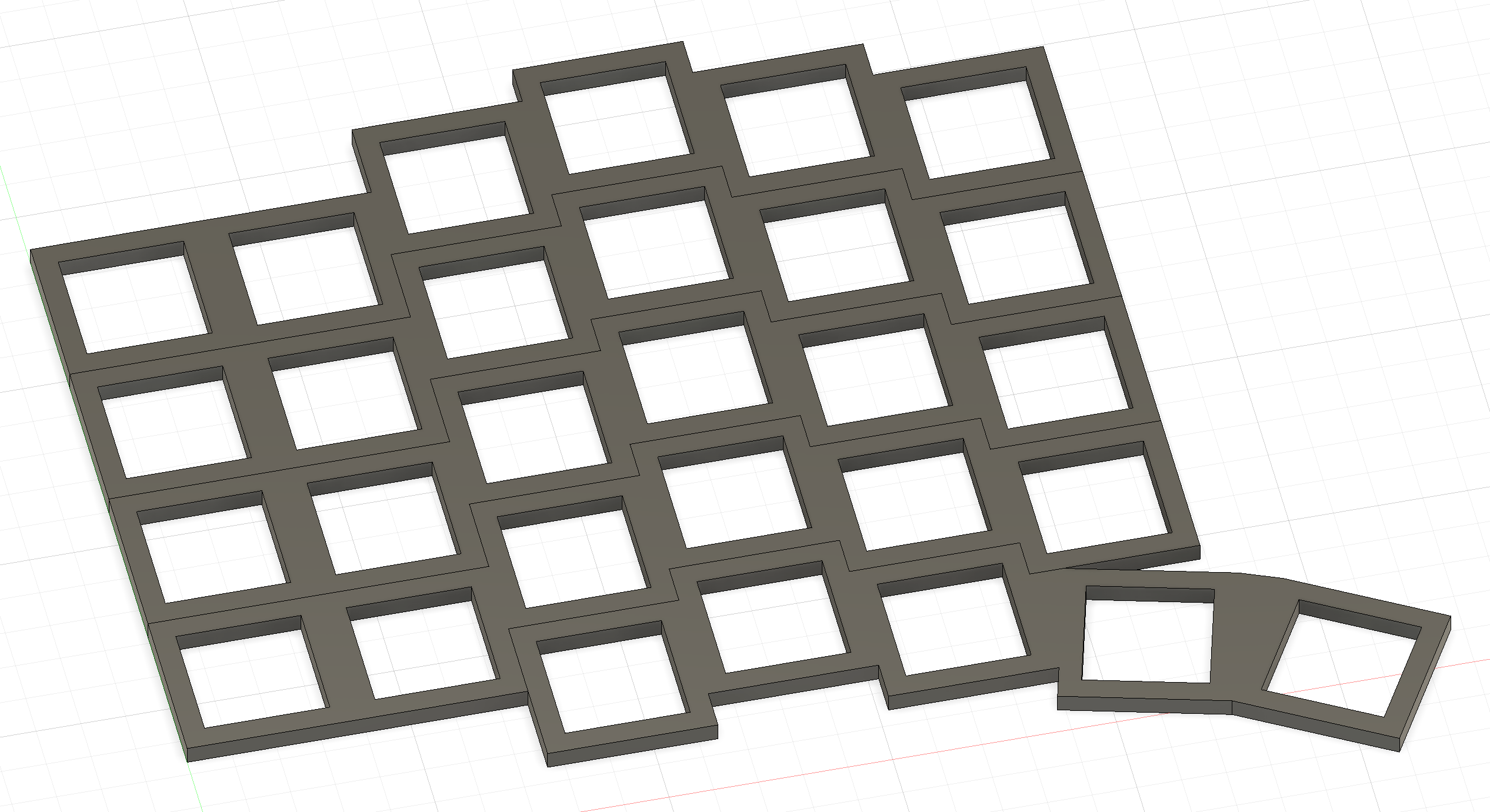
Rather than cutting holes in a plate, extrude just the key «margins» of a single row and repeat that
Taking inspiration
In the previous post, I mentioned my sources of inspiration. My design borrows some traits from them.
All of them include thumb keys at an angle. Lily58 and Sofle were the inspiration to have many keys. Totem was the inspiration to make my keyboard wireless and use the Seeed XIAO BLE microcontroller. Sofle was the inspiration for making my keyboard low-profile.
Additionally, Sofle V2 has a pronounced column stagger, and it served as a reference for key placement on Hovert60.
I want to note that TOTEM has an additional amazing feature – its outer columns are at an angle. It would probably make it easier to use the keys on them with the little finger. However, that would require heavy modifications to my design, so I didn’t do anything like that. Maybe next time.
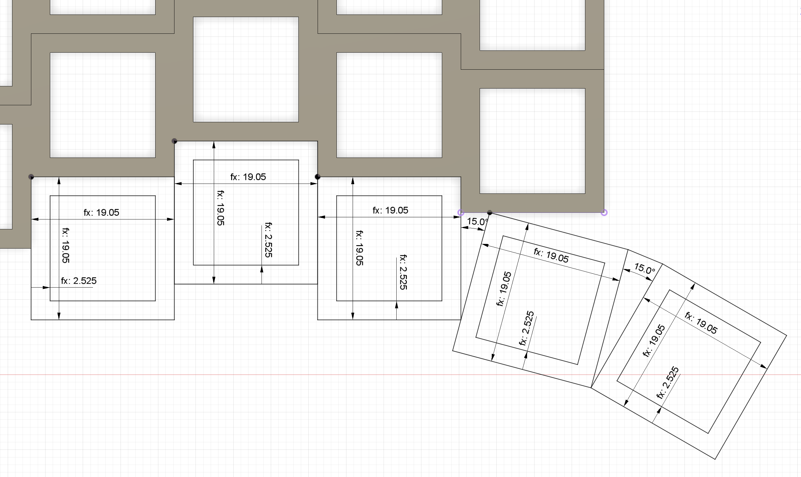
Designing a curved thumb cluster
Approaching the finish line
Adding other parts
To estimate what the final assembly would look like, I measured the parts I ordered and added them to the project as simple rectangles. Either way I needed to include the part responsible for mounting the microcontroller into the assembly, as I still needed to create the bottom plate that would fit under it.
Adding a microcontroller breadboard to see how it would look
Together with the battery and the bottom plate, the model looked like this:
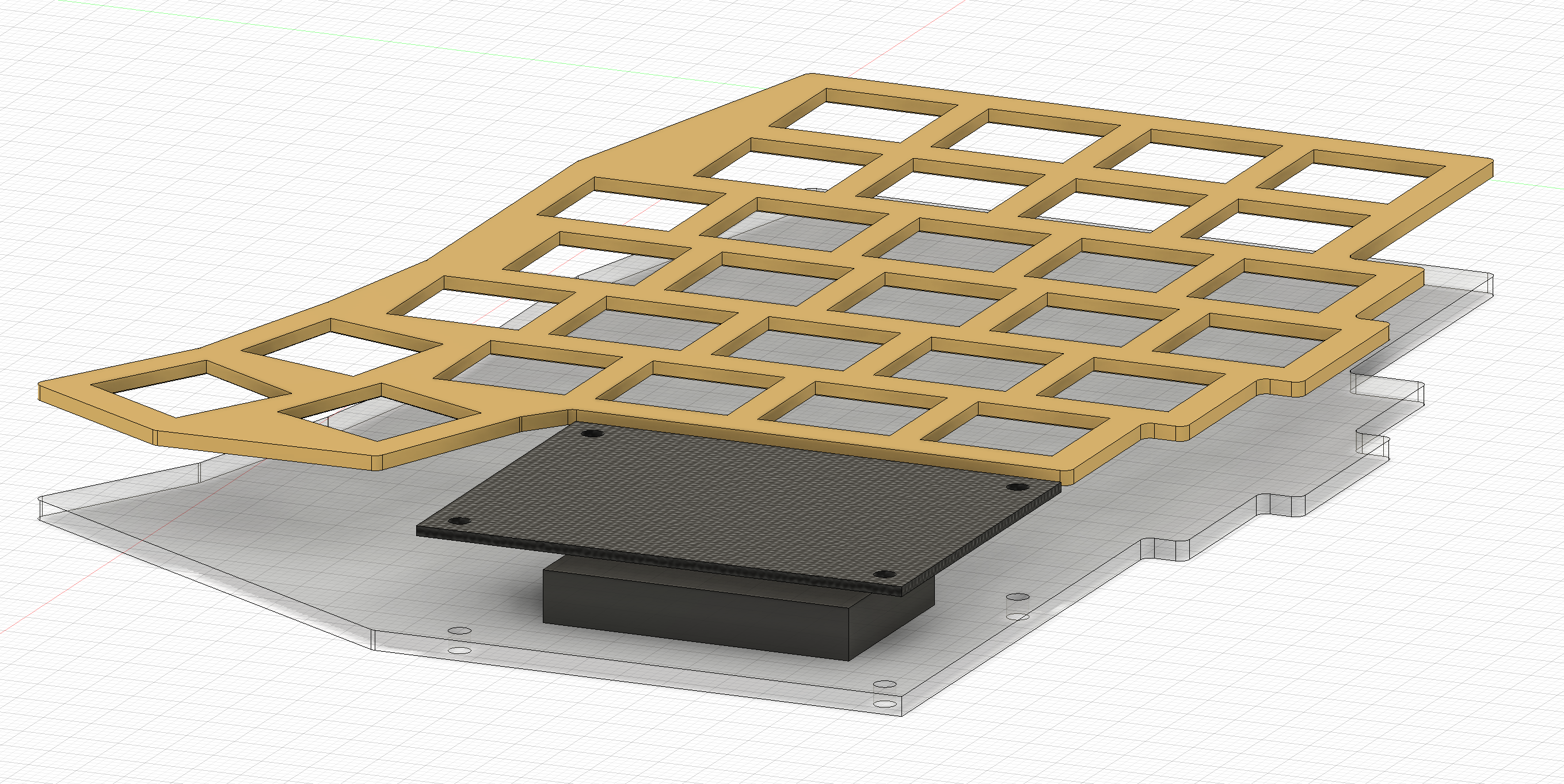
Adding a bottom plate and a battery to see how they fit
Projecting the bottom plate
The bottom plate is actually an interesting part because it’s extremely easy to make. All it involves is creating a new sketch and projecting the top plate and the microcontroller breadboard onto that sketch. Then I only needed to draw 2 lines to join them in a pretty way, and I could extrude the bottom plate.
This is where Autodesk Fusion shines. When I do minor changes to the top plate or the microcontroller part, the bottom plate gets recalculated automatically. Sadly, it’s quite easy to break everything with larger changes, but this feature is still very helpful.
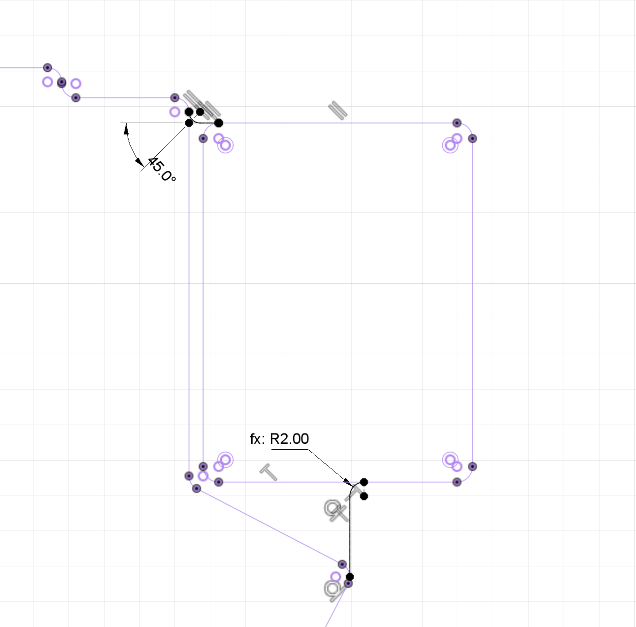
Making fillets on the bottom plate based on projections of other parts
Feature showcase
At this point, I can show you the «almost final» version.
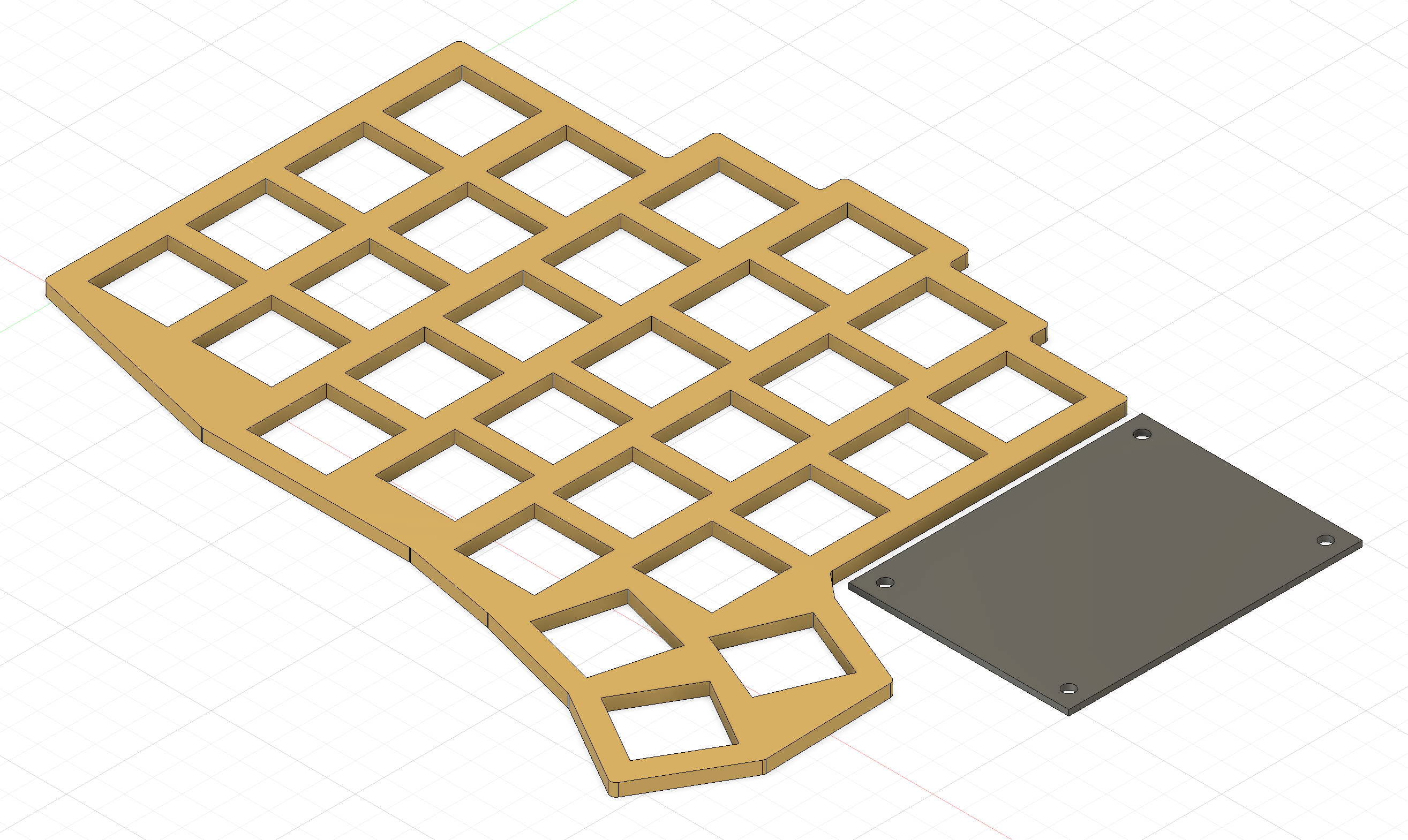
Let’s start with an overview. In the following image:
- There is a yellow front plate which includes
- 30 key holes, 24 of which are aligned in a repeating pattern, and 6 of which are positioned differently so it’s easier to press them with the thumb
- an outer edge that is wider than the gaps between keys to improve rigidity
- 11 screw holes, all of which are on the outer edge of the plate
- There is a dark rectangular part with 4 screw holes that represents the microcontroller mount
- There is a grey transparent bottom plate in the background (it does not have all the screw holes, but it should)
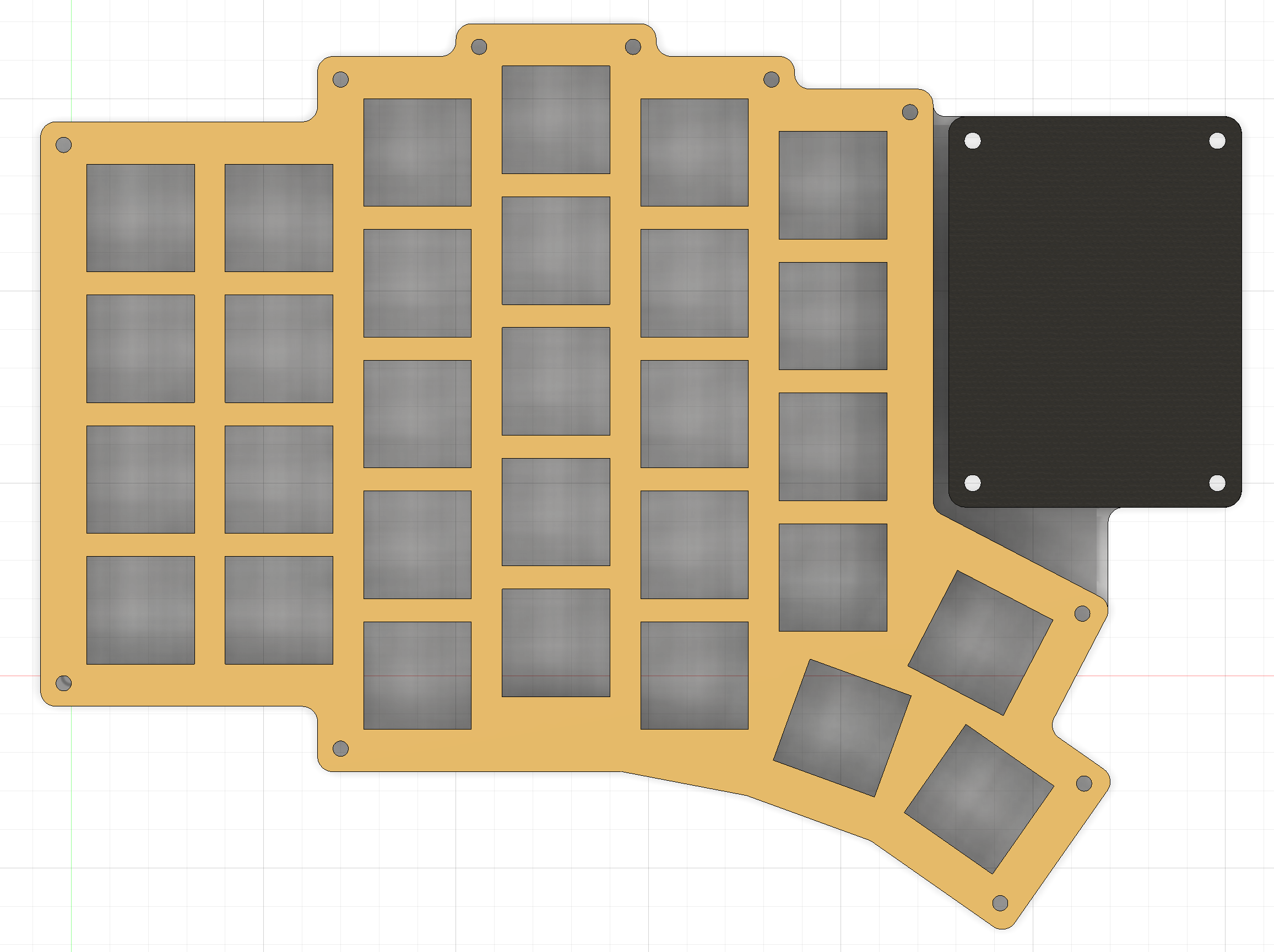
Top view of the «almost final» version
Then, let’s take a look at the sketch of the thumb cluster. Did you notice that there is no additional padding on the outer edge of the keyboard there? That’s because this sketch exists «in the past», before the padding is added. At the same time, it’s still possible to come back to the past and edit it, recalculating everything «in the future» that depends on it. That’s how the screenshot is taken.
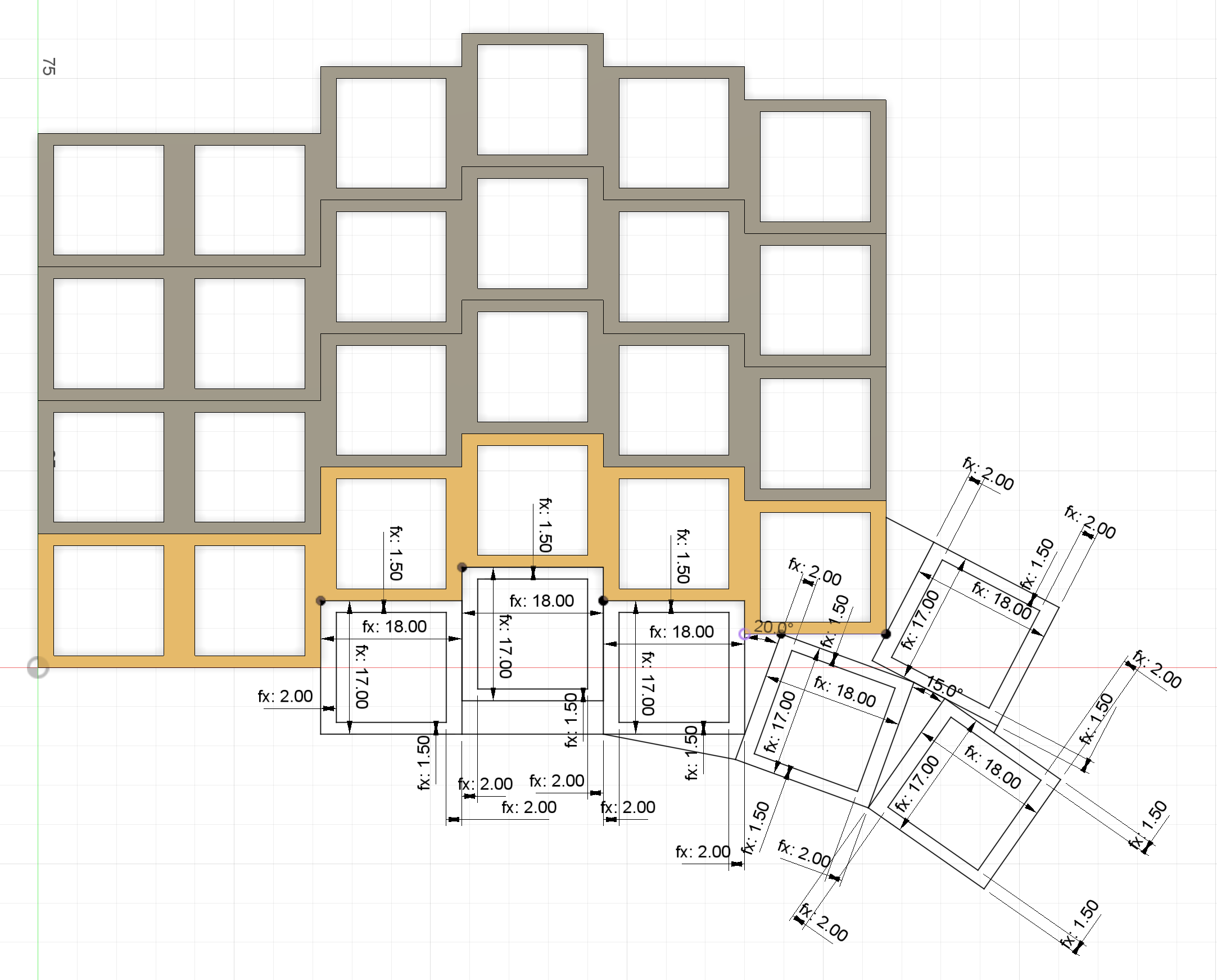
Dimensions of the thumb cluster
The following image shows the «infamous» key switch notches on the bottom side of the top plate. They were not strictly necessary, they complicated the manufacture process, and they are just marginally better than nothing (the switches can still fall out of them if I don’t glue them in). But I wanted them to be there.
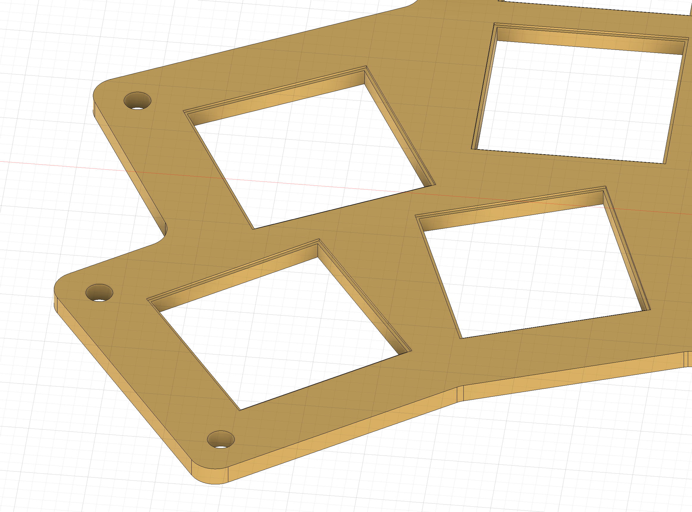
Notches for the key switches to lock in (bottom side of the top plate)
And these are the parameters that I ended up with. There are a lot of them, and some of them are probably not even used now.
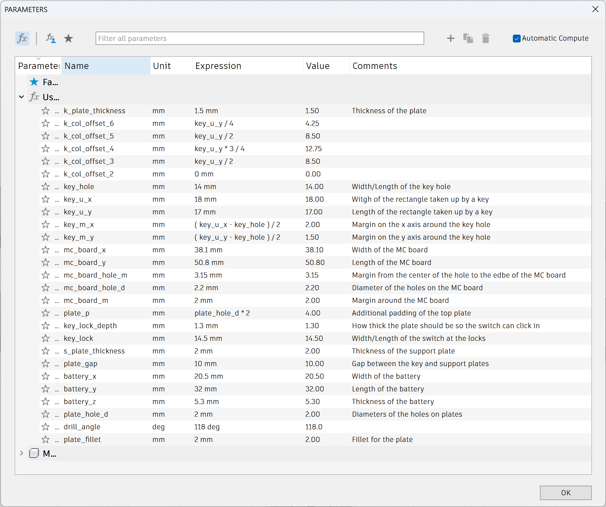
Parameters used in the «almost final» version
What’s next
At this point, I already started doing some cutting tests using the CNC Router.
I tried to run a single test on aluminium, and it went horribly wrong. That’s why I decided to test the design using acrylic first.
There were still a few uncertainties remaining, but they were easy to resolve by trying out different things:
- How precise do I need to cut things? How do I find good settings?
- How many screw holes do I need? Should I put them between the keys as well, and not just on the edges?
Next post will focus on:
- Making a small test component to try out different cutting approaches quickly
- Adding a lot of tweaks to the design
- Learning how to use the CNC router by trial and error